For a deeper look into the process of creating PTMs see ArchX 3 – PTMs and RTIs Explained.
Reflectance Transformation Imaging (RTI) is the new name for Polynomial Texture Mapping (PTM). The PTM techniques, equipment, and software were first developed by three very bright fellows at HP Labs. At WSU’s Arch Lab we are developing our own equipment and a software program to automate the manual processes.
We call our automatic RTI/PTM picture taking equipment the Photo Artifact TurnTable or simply, PATT.

Fig. 1 PATT
PATT is a small robot about the size of a large shoe box. There are many styles of machines (more on this later) but the beauty of PATT is that she can easily be scaled up for larger artifacts and lends itself to experimentation with different types of light since it only has one light source. The light source is a high intensity LED but it could easily be swapped out for IR, UV or any other colors. PATT was designed with experimentation in mind.
Let’s begin by looking at some examples of PTMs/RTIs taken off the HP Labs Website.
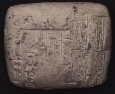
Fig. 2 Clay Tablet Normal Photograph
 Fig.3 Clay Tablet PTM with Specular Enhancement Turned On
Fig. 2 is of a carved tablet. It appears readable but…after creating a PTM and capturing an image of it, Fig. 3, you can see how much more readable the tablet becomes.
So, what exactly is an RTI / PTM?
This is a complicated question with several parts to it but let’s begin with a simple example.
Remember when you were a kid and you were all sitting around with all your friends telling scary stories at night? Then someone would shine a flash light under their face to exaggerate their features? Well that’s where the PTM begins its journey. A light is shined on an object and a photograph is taken. The the light is then moved to a new position and another photograph is taken. The process is repeated over and over again for about 50 photos. Each photograph reveals a different aspect of the object.
The PTM/RTI software takes all of these photos and runs an logarithm on them that allows the light angles to be interpolated to any possible angle. There is much more magic involved but we will talk about that a little later.
Let’s look at a printing plate that was found in Detroit at the site where the Renaissance Center now stands. A WSU team of archaeologists undertook an excavation before the construction of the buildings. Fig.4 is a portion of a printing plate that was unearthed. We rediscovered it in our collections recently in a project called Unearthing Detroit. (If you follow this link, scroll down and you will see two scientists working at a light tent. The fellow in the blue shirt is me! The other fellow is my colleague, Mark Jazayeri.)
Fig. 4 Printing Plate
The Unearthing Detroit team tried various techniques to read the printing plate including inking the plate (not with actual ink!) and trying a pressing. So then it was tossed my way to have a go at it with PATT.
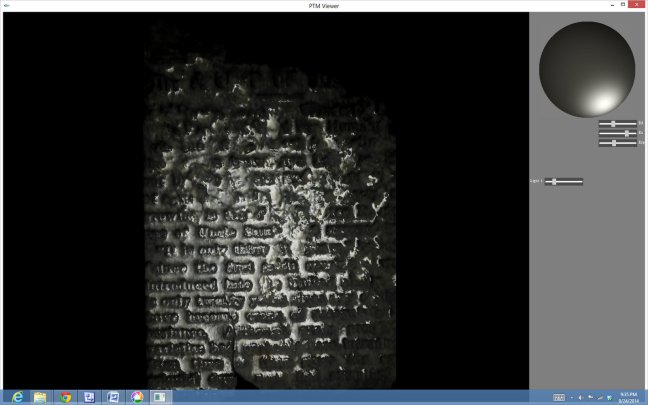
Take a look at Fig. 5. This is a screen capture of the PTM of the printing plate. On the actual PTM moving your mouse pointer around the sphere in the upper right will allow you to change the light angle. Note: There was no additional cleaning or prep done to the printing plate between Figures 4, 5, & 6.
Fig. 5 PTM of Printing Plate
Fig. 6 shows that by turning on Specular Enhancement you can bring out even more details. Again the upper right sphere must be manipulated to obtain the best possible image for different portions of the object being examined.
Fig. 6 Specular Enhancement Turned On.
Through PTM or RTI we were able to read the printing plate and find a copy of the original publication. It was a US Government document about agricultural practices published in 1910.
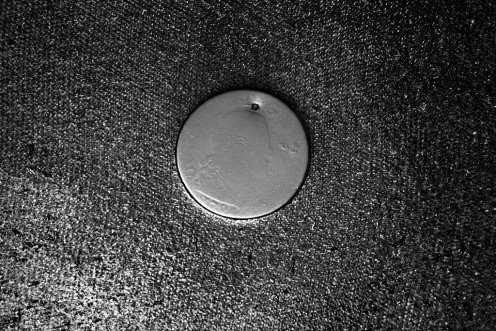
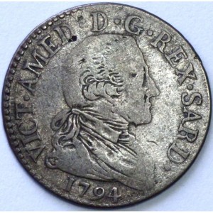
Sam, one of our grad students brought in a coin to see if we could identify it. The front side of the coin appeared worn beyond recognition. Fig. 7 shows a screen capture of the PTM we created. Look closely and along with the date you will see the side profile of a face with a pony tail to the left.
Fig. 7 Sam’s coin date turned out to be 1794
Fig. 8 A similar coin found on line.
Magic
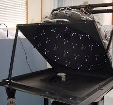
Now in your basic PTM anywhere from 30 to 75 photos are taken with the camera in the same position and the light coming from different angles all around the object. PATT creates 40 photographs. Fig. 9 shows a dome of lights (raised so you can see the lights) above an object to be photographed. During the photographic process only one LED bank would be turned on at a time.
Fig. 9 Dome of LEDs
This system requires a control system to turn on one LED at a time and snap a photograph. Repeating the process until all angles have been photographed.
Magic Trick #1 Virtual Light Positioning
The first thing the PTM software does is to take all of these light positions and interpolate them so that on screen you are presented with the image of the object and (here is the COOL PART) you can manipulate the light anywhere around the object, to any angle, in real time while you look for the best angles to reveal features of the object.
Magic Trick #2 Specular Enhancement
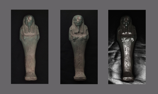
Take a look at Fig. 10. Here we can see the an Egyptian Ushopti, Re-imaged using Light Positioning, and Re-imaged using Sepcular Enhancement..
Fig. 10 Egyptian Ushopti (HP Labs PTM’s used in this example)
We see something all together different when we turn on Specular Enhancement.

